About Us
About Us
Zhejiang Honghua Machinery Plastic & Rubber Co.,Ltd was set up since 1986, for long time, We always abide by the purpose that ‘Stable creates value’ to provide value added services to our customers. The company covers the area of more than 20,000 square meters, Our company is specialized in manufacturing fully automatic plastic machine, such as Plastic Sheet Extrusion line, Thermoforming Machine and Cup Printing Machine.
With a batch of senior technical experts, our company has obtained ISO9001 Quality System Certificate, and CE Certificate which combined design, development, manufacture, installation and service in to system. The products are sold to over 30 countries, such as European, Middle East,, Eastern and Southern Asia, the products also be highly praised and appreciated by consuming public.
Read More


Products
Hot Products
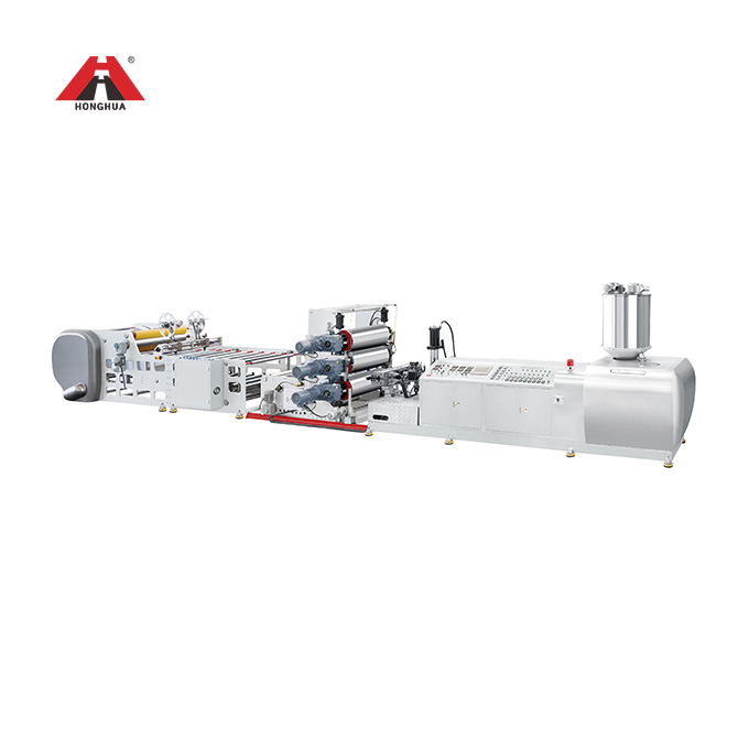
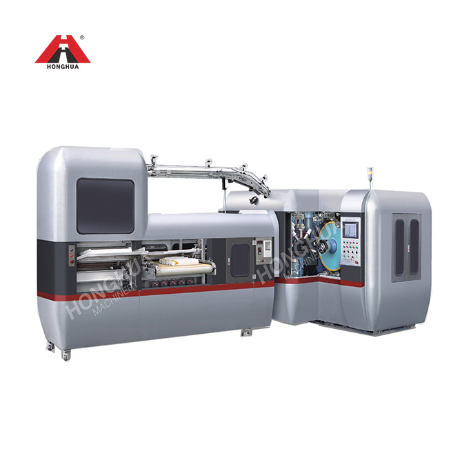
HSJP-100 PET
Twin Screw Extruder
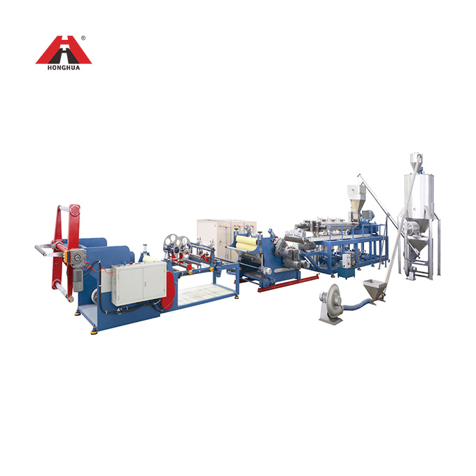
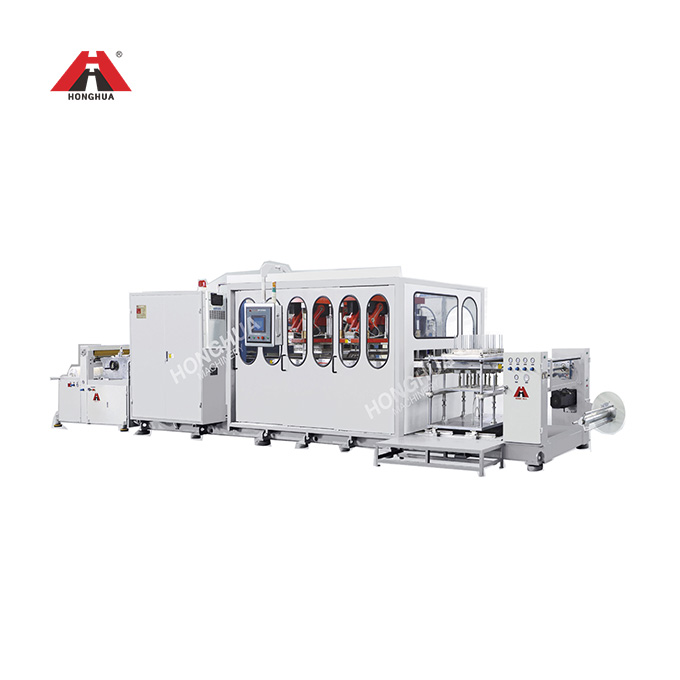
HSJP-100B
Plastic sheet Extrusion Line
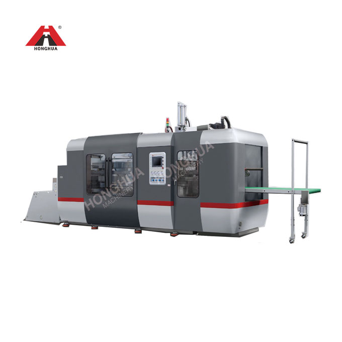
HFM-700B
Plastic Cup Thermoforming Machine
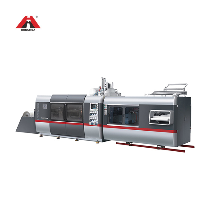
HSC-750850
Full Automatic Plastic Thermoforming Machine
COMPANY NEWS